Well, since my last posting, I have been gathering bits. I have all the required fenders to form the pontoons and head fairings. Last weekend, my un-indicted co-conspirator, Dave Ullman flew in and we put some serious time into making sure the sketches could be matched with sheet metal reality. Well, in fact we matched them to duct-tape reality. Before cutting any steel, we made a mockup of foam and duct tape on the ’32 Buick chassis. What with the shortened days of a northern New York November on us, we could only do the skin on one half the car, but we framed in both sides, to be sure it will all fit and work.
Speaking of fitting, we were REALLY concerned that if we kept the body narrow enough to look right, our four cheeks across would be a bit pinched! After running the Great Race in the mighty 61 Imperial (wide enough for four normal folk to sit side-by-side; this looked to be a real issue. We did lots of static measures, sitting in the house, on the floor, and in chairs; but nothing tells the truth like getting in a cockpit with real controls in front of us.
We divided the plan and elevation views into 5 sections: at the radiator, the firewall, cowl, seat backs, and midway down the boattail (right over the real axle). We made measured cut-outs in 1-inch rigid blue foamboard that was really meant for insulating houses. We used more of the 3/4 inch PVC piping to make stringers at the base and shoulder lines of the torpedo body. Then we started covering it with strips of the universal material, Duct Tape. The results are shown below.
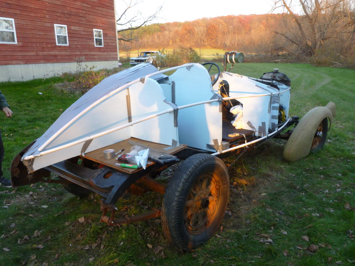
Foam & Pipes Inside...
Duct Tape Outside!
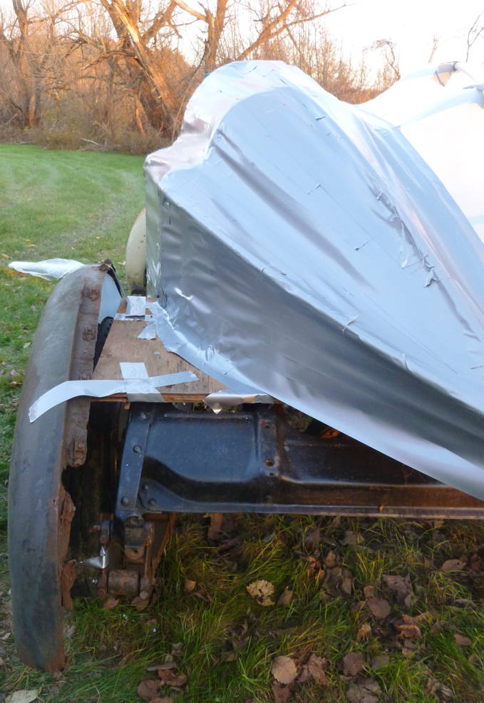
The front fender pontoons are the rears of an MG-A. The rears here are from 1938 Chevys. In the barn are more of each, that will be twin-welded to form full pontoons, but this shows how they will look. The fronts need a lot more trimming than the rears. Here’s a close-up of the engine bay; with a rough marker trace to show the cut lines still to come:
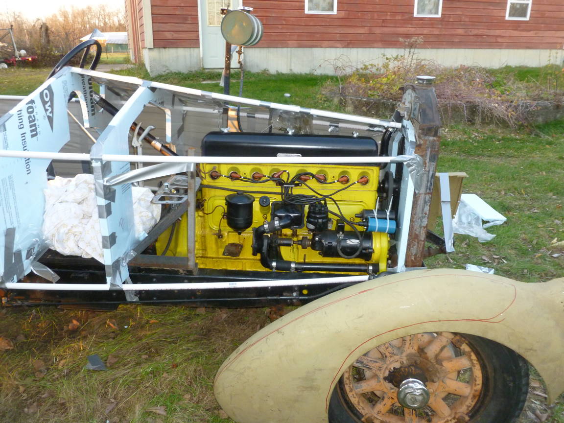
Room for the Power, Note Red Cut Guide on Fender
Here’s a pair of images showing front and rear views:
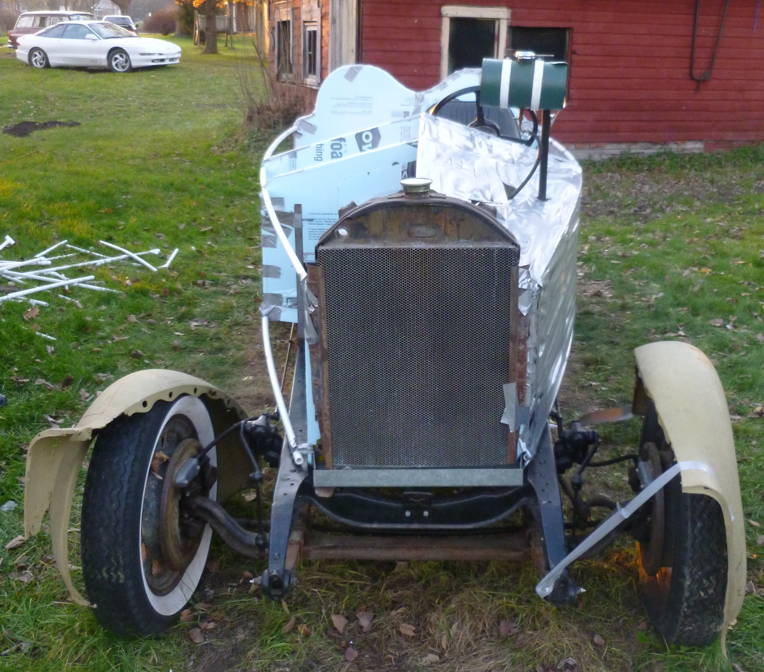
From the Front, A Torpedo, Indeed
From the Rear, Boattail & Fairing
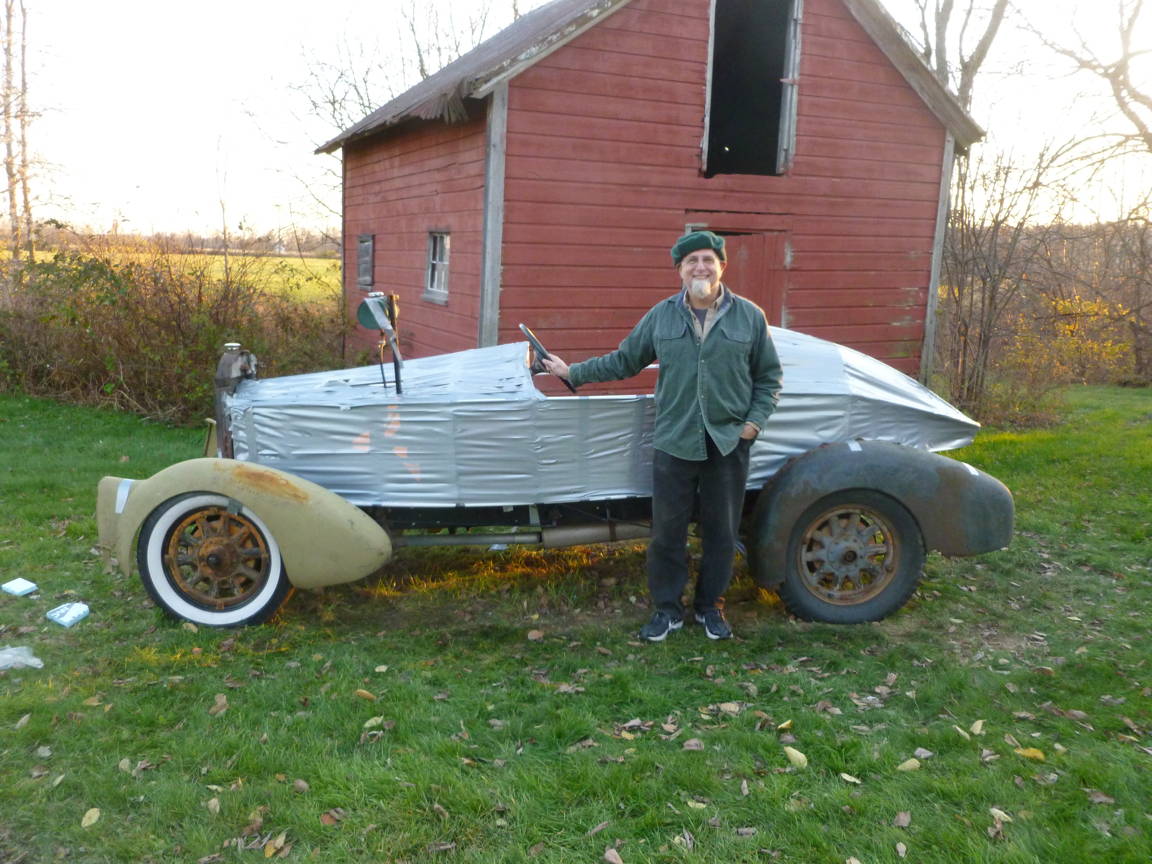
OK, so maybe it takes a little imagination still, to see that we can really do this. Does it help to compare the DuctTape Special to the Rendering of HowItWillBe? Let’s see:
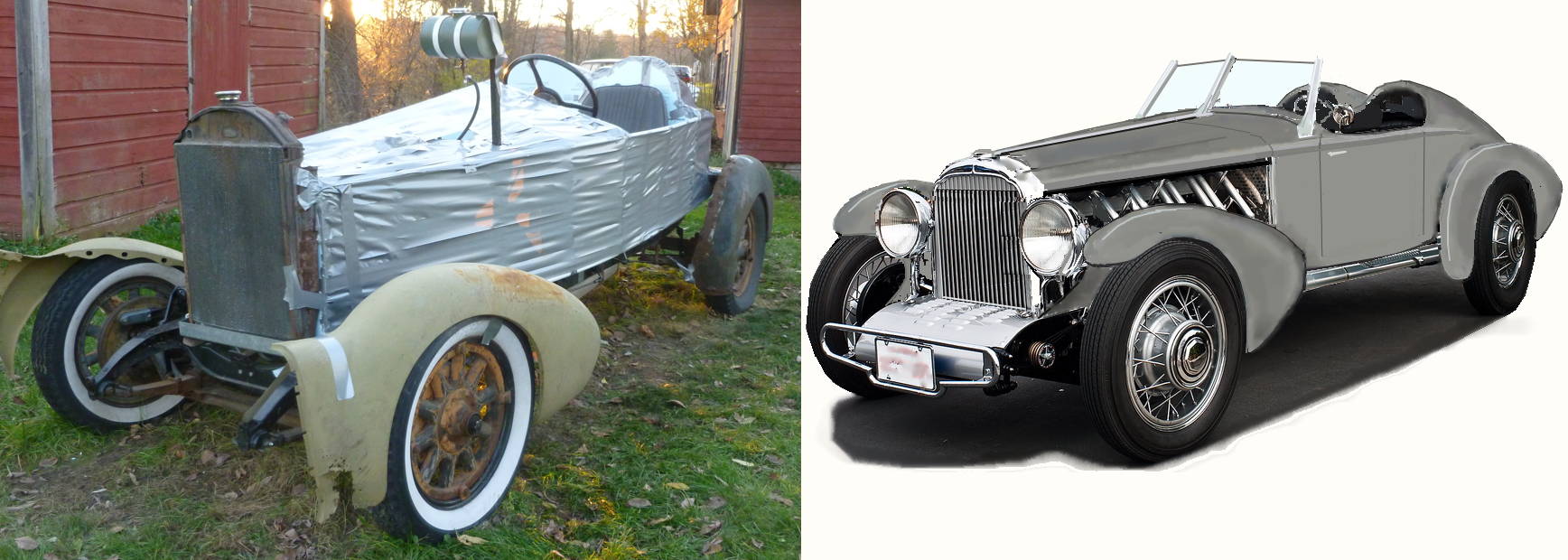
Squint and It Almost Looks Real...
No? Well , WE can see it. And yes, we know – it needs a new, lower radiator. And look at those speed ripples in the duct tape – it almost looks fast just sitting there!
Here’s another way to see how close our design is to what really fits on these mighty wheels. The elevation we built to, overlaid on the profile photo (with rear clearance dropped to correct for no body weight now):
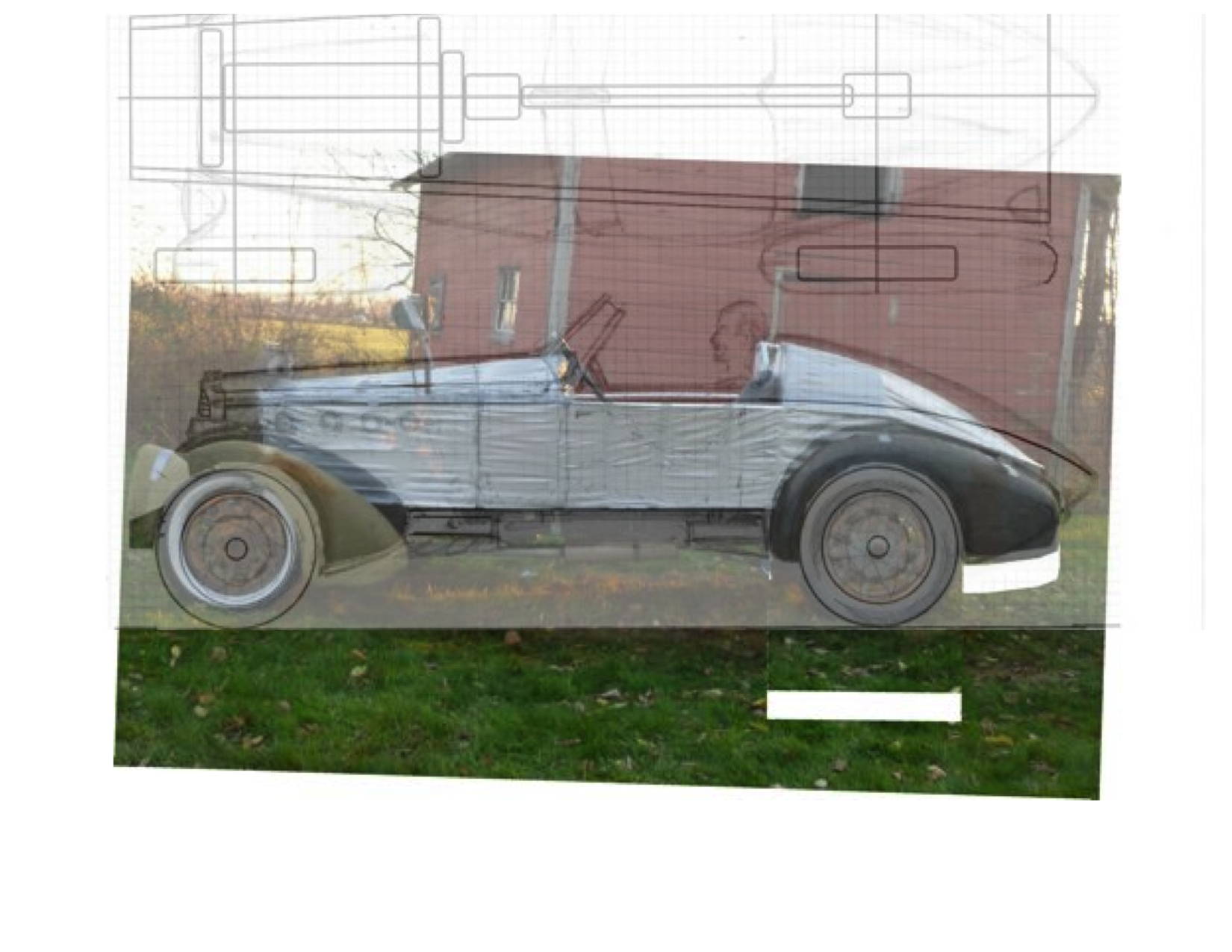
The Plan, Overlaid on The Duct Tape Special!
Looks pretty close, Eh? Except… You might notice that the DuctTape hood looks short, and the DuctTape boattail looks short. That’s because of the parallax – those bits are farther from the camera than the fenders, so they appear smaller. For instance, a look back at the engine bay image above will show that the radiator really is in line with the front axle, but it looks way back here. With a little math, we can correct this photo effect, and lengthen the torpedo body behind the fenders. Here’s how that looks in overlay:
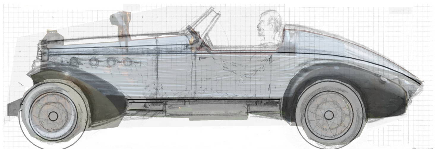
Match of the DuctTape Special to the Plan!
Not Bad at ALL! Are you as psyched as we are yet?
This next week, we get all our wire wheels in a second chassis. The plasma welder is all warmed up and as soon as I bring home a bottle of shield gas, we can start in on the forming and joining. What’s ahead:
Front Pontoons: Outer fenders need to be re-radiused (MG-A tires are 27 inch diameter, these are 29); Inner fenders need to be cut to fit the bridging pieces, made from original Buick fenders, that will rise from the chassis rails and allow the steering clearance. Inner and outer need to be trimmed to their new leading edge shapes, then the bridging, inner, and outer need to be welded into single assemblies. In fact, these will not be done all at once, because the bridging, especially must be sized to the right height, once the suspension is loaded with bodywork.
Rear Pontoons: Outer Fenders need re-radiusing, too. Inners and Outers need some turn-under hammer work at their lower trailing edges, so they rise like the MG pieces in front. Bridging here is simpler, and consists of planar-bent covers between the boattail and inner fender. These will be removable, too.
First up, though is the cowl and hood. To get the unbroken line that sweeps from grille to tail (and to make room for our old-guy foundations in side-by-side seats) the 32 Buick is too narrow and tips in between cowl and hood. These parts will need to be made from scratch. However, I have in mind to make the cockpit and doors, at least from existing stuff. In particular, we have a donor MG-A in the field (sans rear fenders) – and they have a really nice cockpit line:
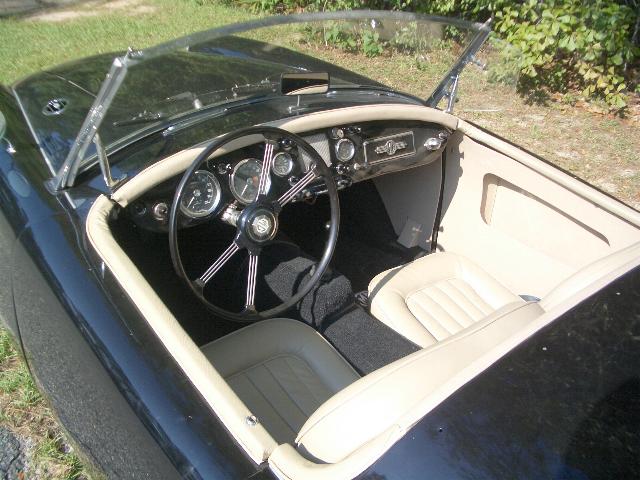
Look at that Nice Cockpit and Edging
NO, that’s not the donor car , but you get the idea. There’s a nice crease in an MG-A, between fender and hood, that might tie in well with the ‘shoulder’ crease on the 32 or 33 Buick grille! I confess, I’ve become partial to the 33, as it has a Vee prow, where the 32 is flat. Think it doesn’t matter? Just compare these two views below – same car, same rendering – but look how much more dynamic it is with that front Vee! It’s going faster already. Just below that a quick paste-up to show how the MG cockpit can fit into the scheme.
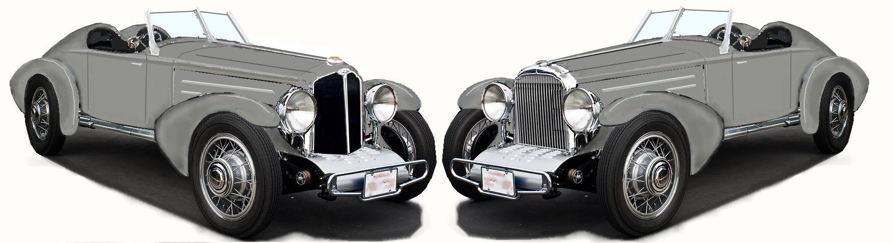
33 Grille at Left vs 32 Grille at Right
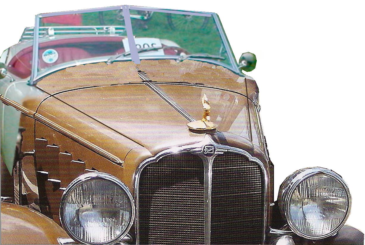
A Hint of MG Meets Buick: Note Hood Crease to Cowl Crease
Yes, there’s a two-piece windshield fitted here, and some minor cheats through the magic of computer wiggles, but you get the idea, I hope. No luggage rack for us, either. Which brings up and interesting question: how to access the storage in the boattail! The surfaces are two complex for cutting a normal trunk lid. Maybe some behind the seats and maybe a little golf-club door in the side behind that. I dunno – in many ways, thinking and sketching is as much fun as actually building the car. Starting next week, with parts moving to the (heated) shop of Bob Ensign (www.ensignautobody.com), the work begins in earnest!


I don’t think the duct tape will pass inspection!